Home page
Back to Thunder wiring menu

Westone Thunder active guitar wiring - fault finding (Circuit version 1)


If the circuit fails to work at all, it is most likely due to a power supply fault. or a short circuit. Once these possibilities are eliminated, check the action of the active on/off switch and the pots.

1 Checking for shorts and testing the power supply


All of the resistors are mounted vertically and usually in the same orientation as nearby components, check that no component leads are shorting out
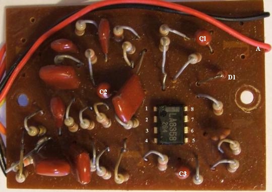
The components on the PCB are all operating well within their normal parameters, it is unlikely that any will fail, however capacitors can leak as they age. Check the board for signs of leakage, especially from the Tantalum capacitors (Marked below as C1, C2 and C3)
pcb top view
With a lead plugged in to the guitar check the voltage between pins 4 and 8 on the op-amp, using a multimeter set to a 20V range or higher (Negative lead to pin 4, positive to pin 8). With fresh batteries in, you should get a reading of about 18 to 19 volts. If you do, go on to the next section. If you don't, there is a power supply fault.

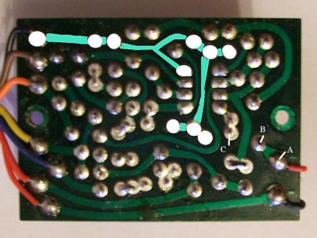
Check the voltage between  pin 8 and the earth on the jack socket. If you get a reading of 18-19 volts here but not between pins 4 and 8 of the IC there is probably an earth fault or the diode (D1 in the picture above) is faulty. Remove the board from the backplate and unplug the guitar and check the continuity of the earth wires to the pots and the PCB. Using the earth connection on the jack as one test point, check the resistance between that point and the backs of the pots and the points/tracks on the PCB that connect to earth. All should read zero resistance.  The highlighted area in the picture below shows the tracks and solder joints on the PCB that are connected to earth. If there is zero resistance between these points and earth, check the diode (D1 in the picture above)

The diode connects across points B and C below. Plug the guitar in and check the voltage at point A, it should be the full battery voltage. Check point C, the voltage should be slightly smaller. If there is a reading at A but not at C the diode is faulty. Replace it with another (Use a 1N4148) or a wire link since the diode is not strictly necessary.

If you do not get a voltage reading at pin 8 or point A, check the continuity of the battery leads and that the battery negative connects to earth when a jack is inserted.


pcb bottom

2 Testing the pots and active on/off switch

These tests should be conducted with the guitar unplugged and the active on/off switch in the on position.

Check the resistances between the wires on each pot. These readings are taken from my Thunder IIA, due to the varying tolerances of components your readings should be within plus or minus 10 per cent of these figures.

Tone pot - .
Red wire to green wire : 0k at full treble, 170k at centre position, 194k at full bass
Red wire to orange wire (May be yellow) 184k, 161k
at full treble, 0k at full bass

Active gain pot -
Blue to red wire - at maximum gain  0k, at minimum gain 62k
Red wire - at maximum gain  62k, at minimum gain 0k

If your readings are substantially different, check the continuity of the leads from the pots to the switch and PCB, if there is no continuity fault replace the pot(s)
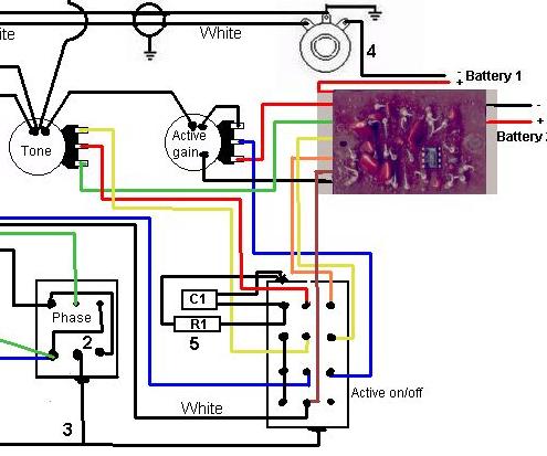
pot connections

Testing the active on/off switch - with the active on/off switch in the on position, oriented as shown above, check the resistance between each terminal in the vertical centre column and the terminal to the right of it, there should be zero resistance between them -

On the top row, the red wire from the tone control should connect to the orange wire to the PCB
On the second row, the orange or yellow wire from the tone control should connect to the yellow wire to the PCB
On the third row the blue wire from the volume control should connect to the blue wire to the PCB

If any of those connections does not show zero resistance the switch is either dirty (Try switch cleaner) or faulty and should be replaced.